Truss System Design Using Ansys APDL
The aim of this study is to design a truss system that meets the desired conditions.
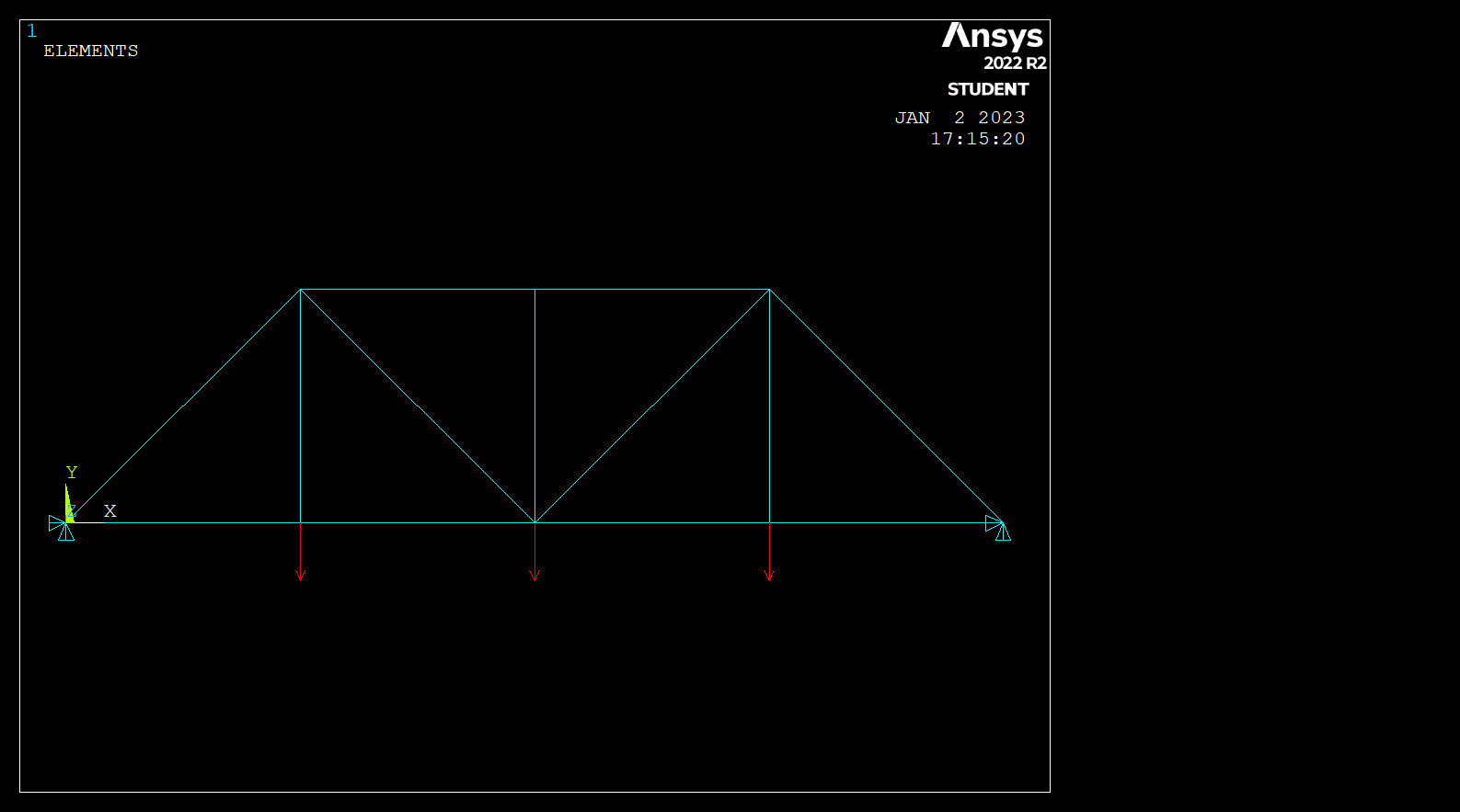
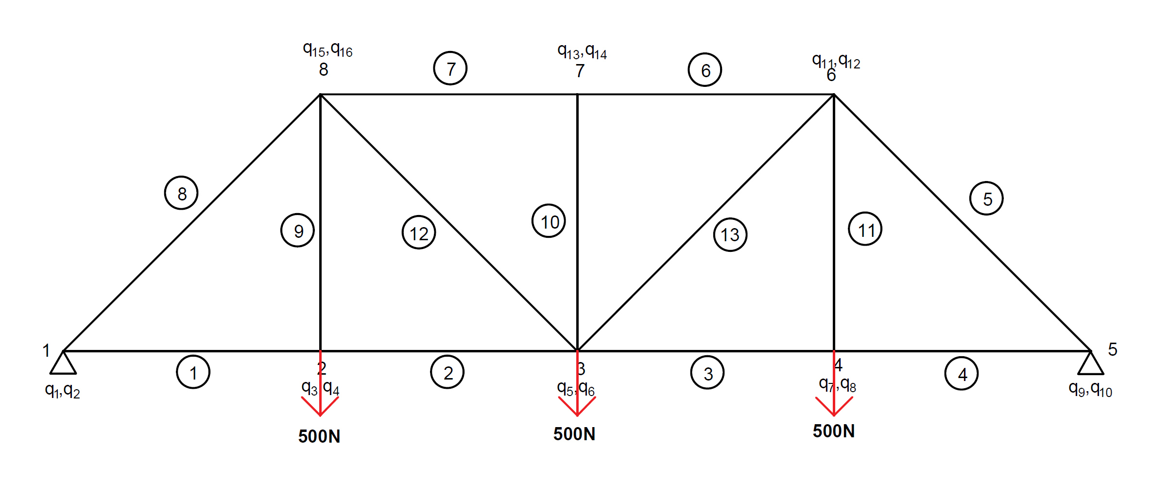
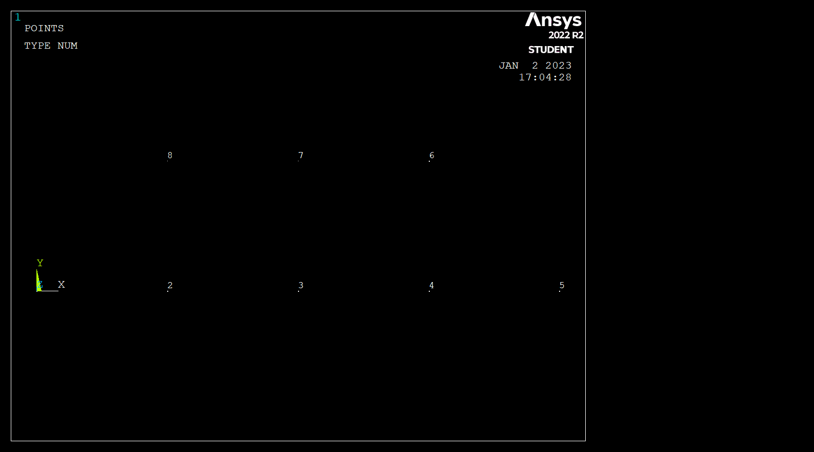
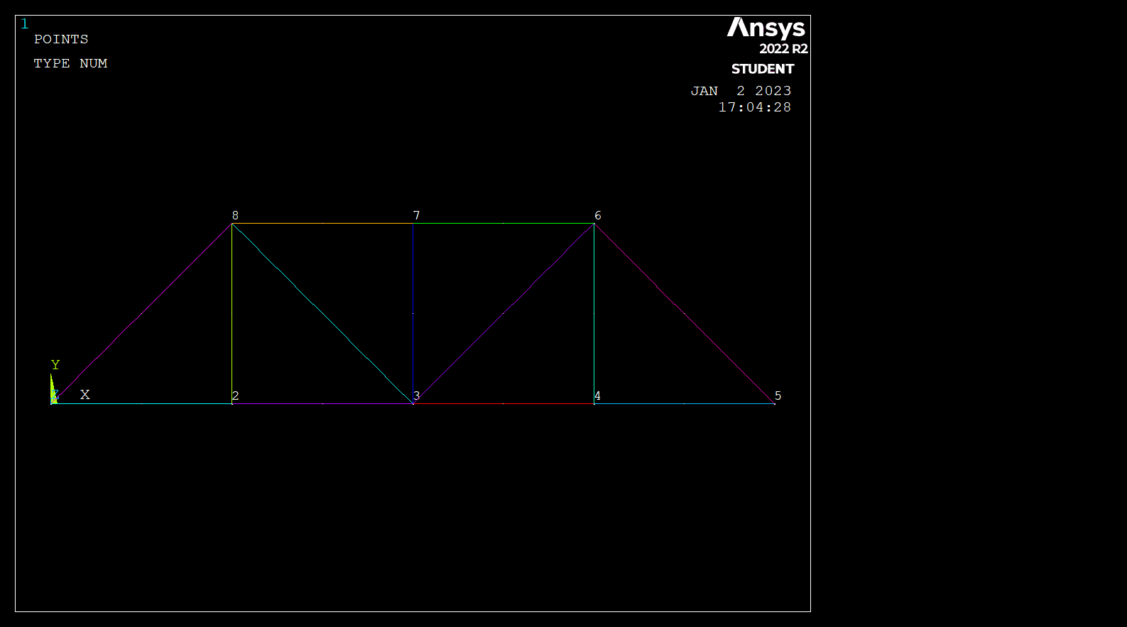
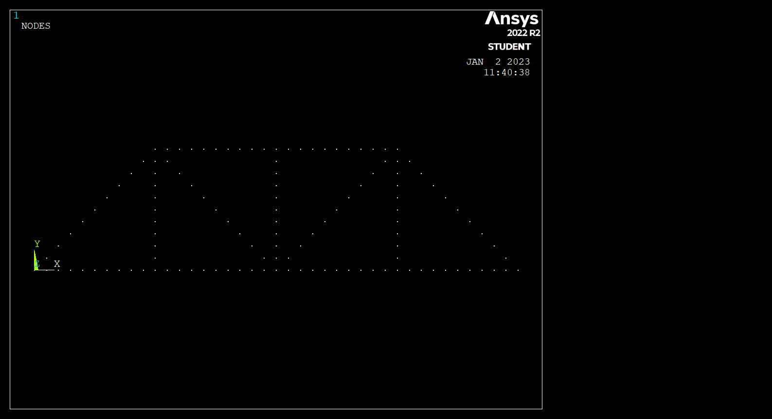
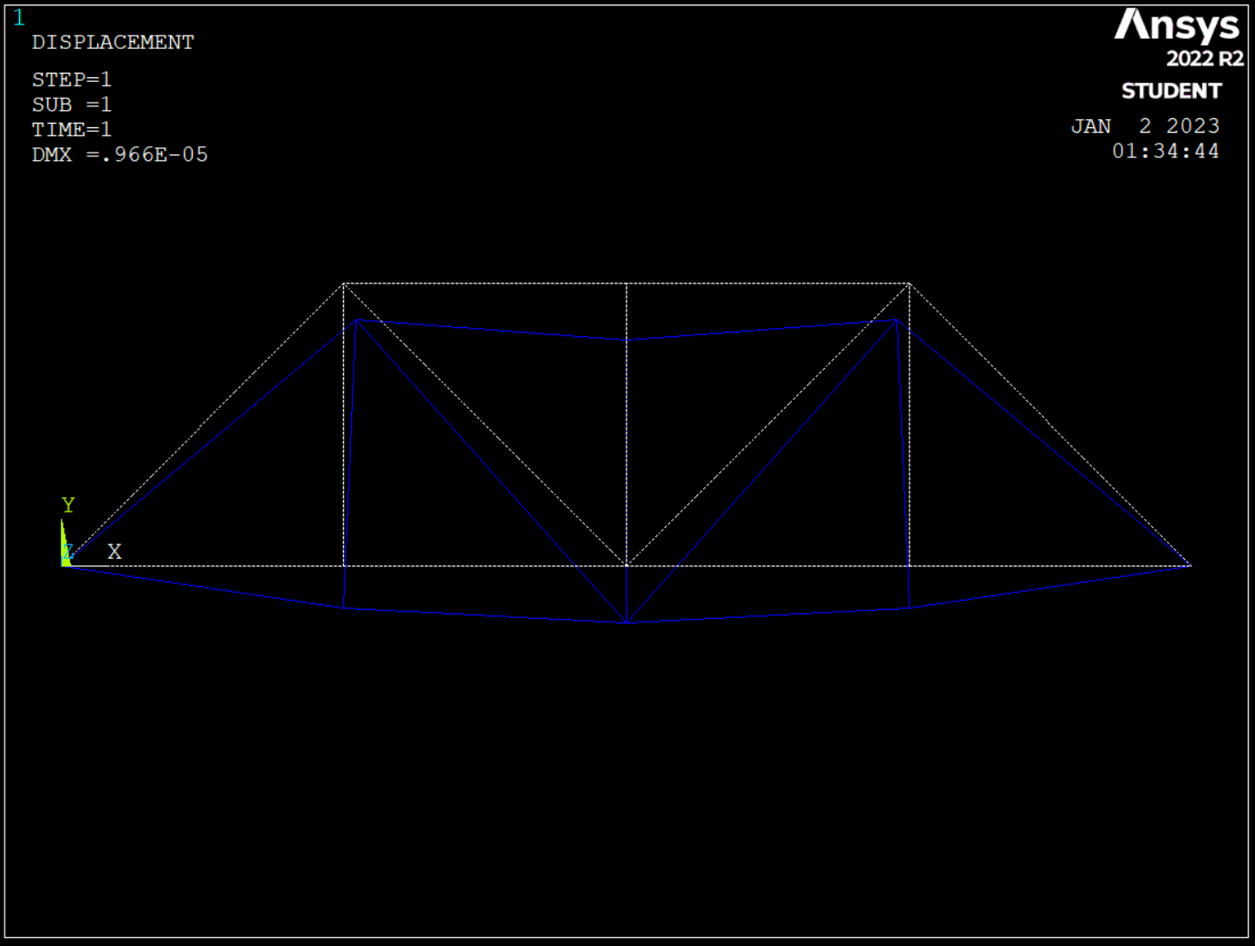
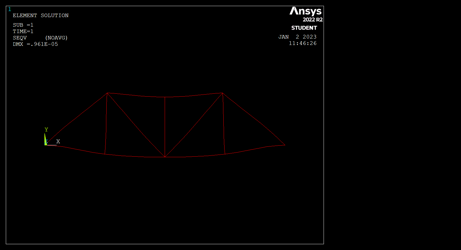
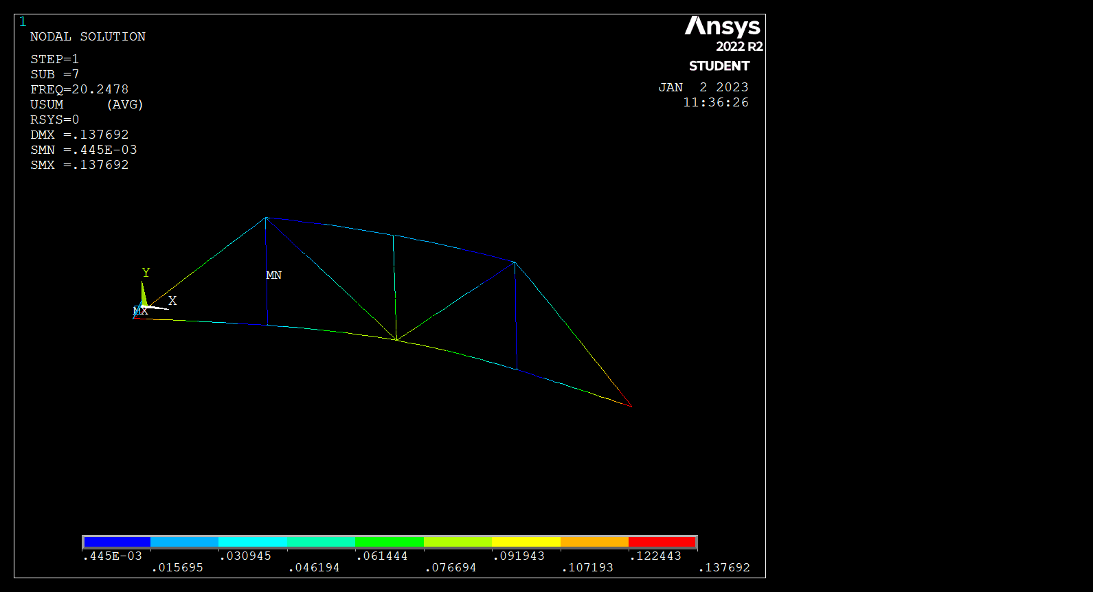

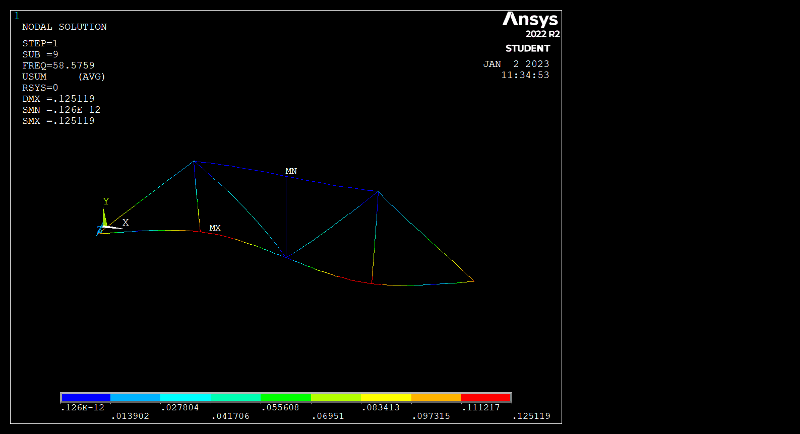
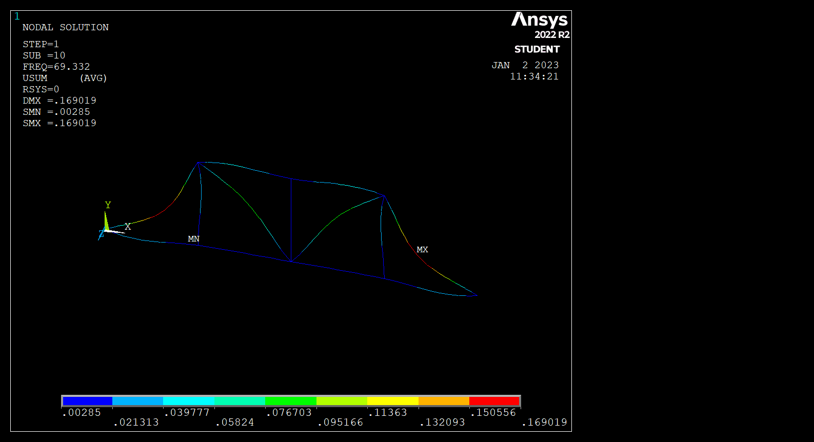
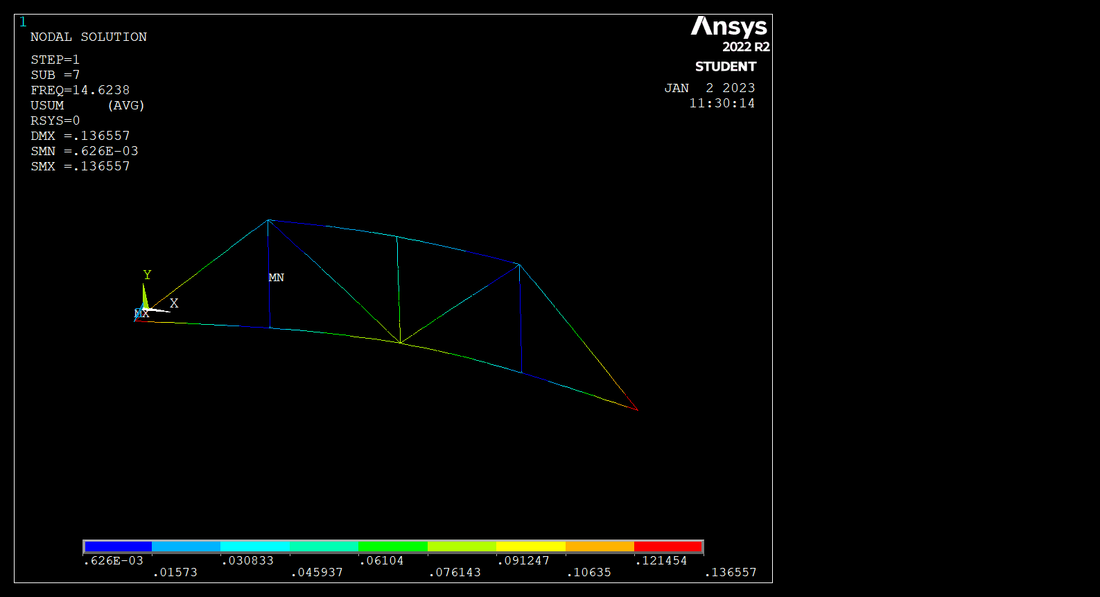
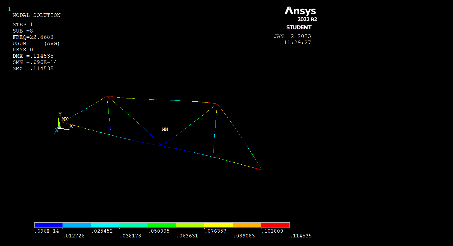
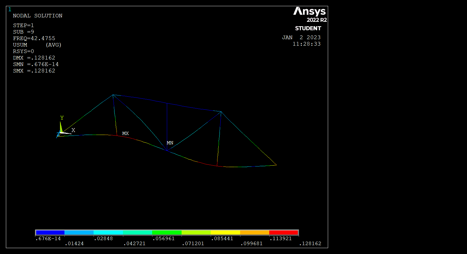
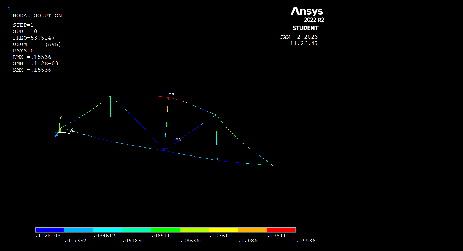
A truss system consisting of 8 nodes and 13 elements was designed. In the first stage, the element’s directional cosines were calculated. Then, the stiffness matrices of elements were calculated. After that, a global stiffness matrix was created. Using the elimination method, the rows and columns on the global stiffness matrix corresponding to the supports with zero displacement values were deleted. Then, the displacement matrix is obtained by taking the inverse of this matrix and multiplying it with the force matrix. Then, the displacement matrix values were replaced in the relevant formula and the element stress values were calculated. Finally, the reaction matrix was calculated by multiplying the global stiffness matrix with the displacement matrix and subtracting the force matrix. All calculations were done in MATLAB. It was simulated in Ansys APDL and compared with the calculated values in MATLAB. Desired Conditions Minimum elements number: 7 Element stiffness and global stiffness matrices will be obtained for two different section states(square, I section). The displacements of the nodes, the element stress value and the reaction forces of these two cross-sectional states and the cage subjected to at least three external loads will be found. For the LINK180 and BEAM188 elements, the desired values in the 3rd item will be obtained with ANSYS Mechanical APDL software and compared the results. By using the BEAM188 element, the mode shapes related to the first 10 natural frequency values of the truss system will be found.
You can use this link for see all project files.